Reference - https://www.embedded.com/usb-type-c-and-power-delivery-101-ports-and-connections/
USB Type-C and power delivery 101 – Ports and connections
USB Type-C is the newly introduced and powerful interconnect standard for USB. When paired with the new Power Delivery (PD) specification, Type-C offers enhancements to the existing USB 3.1 interconnect that lower the cost and simplify the implementation of power delivery over USB. From a form factor perspective, the USB Type-C connector combines multiple USB connectors – Micro-B, Type-A, and Type-B – in a reversible connector measuring only 2.4 mm in height (see Figure 1). Type-C allows developers to also combine multiple protocols in a single cable, including DisplayPort, PCIe or Thunderbolt. Bandwidth is double that of USB 3.0, increasing to 10 Gbps with SuperSpeed+ USB3.1. Finally, the USB Type-C connector can deliver up to 100 W. This enables a wider range of applications to operate using USB (see Figure 2). For more details, watch An Introduction to USB Type-C video and Type-C Basics.
In this two part series, we describe power delivery with USB Type-C, starting with ports and connectors in this article, followed by the power delivery protocol in part two.
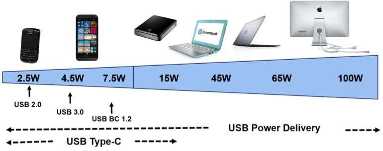
Figure 2. Power Delivery enables a wider range of applications (Source: Cypress Semiconductor)
USB Type-C Protocol View
USB Type-C Signals
Figure 3 show the USB Type-C Receptacle and Plug signals. Table 1 and Table 2 summarize the list of signals used on the USB Type-C interface (receptacle and plug) as defined by USB Type-C specifications.
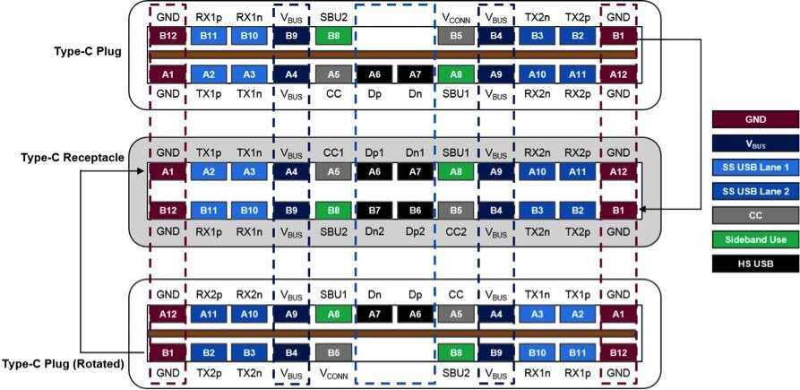
Figure 3. Type-C Reversible Connections (Source: Cypress Semiconductor)
Table 1. USB Type-C Receptacle Signals (Source: Cypress Semiconductor)
| Signal Group | Signal | Description |
|---|---|---|
| USB 3.1 | TX1p, TX1n RX1p, RX1n TX2p, TX2n RX2p,RX2n | The SuperSpeed USB serial data interface defines a differential transmit pair and a differential receive pair. On a USB Type-C receptacle, two sets of SuperSpeed USB signal pins are defined to enable the plug-flipping feature. |
| USB 2.0 | Dp1, Dn1 Dp2, Dn2 | The USB 2.0 serial data interface defines a differential pair. On a USB Type-C receptacle, two sets of USB 2.0 signal pins are defined to enable the plug-flipping feature. |
| Configuration Channel | CC1, CC2 | The CC channel in the receptacle detects the signal orientation and channel configuration. |
| Auxiliary Signals | SBU1, SBU2 | Sideband Use. SBU signals are used in the Alternate Mode supported by the Type-C specification, which enables multi-purposing of Type-C signals for alternate uses such as DisplayPort |
| Power | VBUS | USB cable bus power |
| Ground | GND | USB cable return current path |
Table 2. USB Type-C Plug Signals (Source: Cypress Semiconductor)
| Signal Group | Signal | Description |
|---|---|---|
| USB 3.1 | TX1p, TX1n RX1p, RX1n TX2p, TX2n RX2p,RX2n | The SuperSpeed USB serial data interface defines a differential transmit pair and a differential receive pair. On a USB Type-C receptacle, two sets of SuperSpeed USB signal pins are defined to enable the plug-flipping feature. |
| USB 2.0 | Dp, Dn | The USB 2.0 serial data interface defines a differential pair. On a USB Type-C receptacle, two set of USB 2.0 signal pins are defined to enable the plug-flipping feature. |
| Configuration Channel | CC | The CC in the plug used for connection detection and interface configuration |
| Auxiliary Signals | SBU1, SBU2 | Sideband Use. SBU signals are used in the Alternate Mode supported by the Type-C specification, which enables multi-purposing of Type-C signals for alternate uses such as DisplayPort |
| Power | VBUS | USB cable bus power |
| Power | VCONN | Type-C cable plug power |
| Ground | GND | USB cable return current path |
The USB Type-C Receptacle functionally delivers both USB 3.1 (TX and RX pairs) and USB 2.0 (D+ and D−) data buses, USB power (VBUS), ground (GND), Configuration Channel signals (CC1 and CC2), and two Sideband Use (SBU) signal pins.
To enable Type-C cables to be reversible, the Type-C receptacle is fully symmetrical. All power, ground, and signal pins are duplicated about the symmetry axis, which allows the Type-C plug to be flipped with respect to the Type-C receptacle. The Type-C plug offers only one CC pin, which is connected to one of the CC pins of the Type-C receptacle, to establish the Type-C orientation. The other CC pin is repurposed as VCONN (abbreviation for VCONNECTOR ) for powering the electronics in the USB Type-C plug.
When the Type-C plug is rotated (as shown in Figure 3):
- GND, USB 2.0 and VBUS signals maintain connection. USB 2.0 signals are repeated in the top and bottom rows of the Type-C receptacle to maintain connectivity in either orientation.
- VCONN or CC pin on the plug may be connected to either of the configuration channel pins – CC1 or CC2 of the receptacle – depending upon the orientation.
- One of the two Superspeed lanes maintains the right connection, which must be appropriately routed at the receptacle side using a SuperSpeed mux.
USB Type-C ports
The USB Type-C and Power Delivery specifications have defined different types of USB Type-C ports, based on the flow of data in a USB connection (i.e., data role of the port) and the direction of power in a PD connection (i.e., power role of the port).
The ports based on a data role are:
- Downstream Facing Port (DFP): typically the USB Type-C port on a host, such as a PC or downstream port of a hub, to which devices are connected.
- Upstream Facing Port (UFP): The USB Type-C port on a device (i.e., US Flash Drive, USB Monitor, USB mouse) or upstream port of a hub that connects to a USB host.
The ports based on a power role are:
- Provider/Source: This is a USB port capable of providing power over the power conductor (VBUS ). A Type-C provider port corresponds to the port with Rp terminations (pull-up) asserted on its CC wires (CC1 and CC2).
- Consumer/ Sink: This is a USB port capable of sinking power from the power conductor (VBUS ). A Type-C consumer port corresponds to the port with Rd terminations (pull-down) asserted on its CC wires (CC1 and CC2).
In its initial (default) state, the DFP is the power source and thus sources VBUS . The DFP thus exposes Rp terminations on its CC wires by default. In its initial (default) state, the UFP is the power sink and thus sinks VBUS. The UFP thus exposes Rd terminations on its CC wires (see Figure 4).
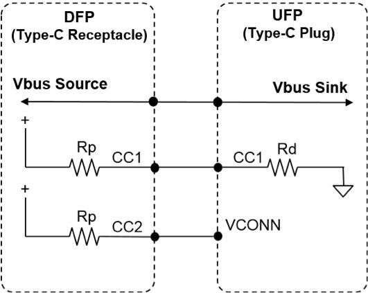
Figure 4. Default Terminations on CC pins for DFP/ UFP. Shown here is the case when a UFP with Type-C plug (e.g. a Type-C dongle or USB Flash drive) is connected to a DFP with Type-C receptacle (e.g. a laptop) (Source: Cypress Semiconductor)
The Type-C and Power delivery specification also define a Dual Role Port (DRP) that can operate as either a Source or a Sink. The power role of the port can be reversed dynamically. A DRP exposes the Rp terminations on its CC wires when acting as a power source and exposes Rd terminations on its CC wires when acting as a power sink (see Figure 5).
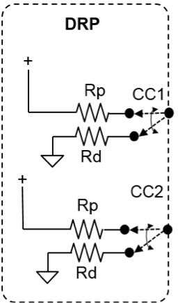
Figure 5. Terminations on CC pins for DRP (Source: Cypress Semiconductor)
A typical DRP device can perform the roles listed in Table 3. PD-enabled USB products such as notebooks with a Type-C port can generally operate as DRPs.
Table 3. Roles of DRP Device
| No. | Port Data Role | Port Power Role | CC Terminations |
|---|---|---|---|
| 1 | DFP | Source (Power Provider) | Connect Rp and disconnect Rd |
| 2 | DFP | Sink (Power Consumer) | Disconnect Rp and connect Rd |
| 3 | UFP | Source (Power Provider) | Connect Rp and disconnect Rd |
| 4 | UFP | Sink (Power Consumer) | Disconnect Rp and connect Rd |
(Source: Cypress Semiconductor)
Detecting the Type-C connection and orientation
As noted above, the USB Type-C specification describes how a Type-C upstream-facing port (UFP) applies Pull-Down resistors (Rd ) on Configuration Channel pins CC1 and CC2 to signify that it is a device and the Type-C downstream-facing port (DFP) is required to have Pull-Up resistors (Rp ) on CC1 and CC2. The resulting resistor divider is used to determine the Type-C device attach and detach. The orientation of the Type-C cable plugs in each receptacle is easily determined as only one of two CC pins is connected across the cable (see Figure 6).
Type-C Electronically Marked Cable Assemblies (EMCA) are cables that require VCONN to power the marker electronics inside the cable. These EMCA’s expose Ra termination resistors on the VCONN pin of the Type-C plug. Non-Electronically Marked Type-C cables do not have electronics inside and have no need for VCONN power. These non-EMCA cables leave the VCONN pin floating on the Type-C plug. For more details on implementing EMCA, see Designing a Type-C Electronically Marked Cable and Designing USB 3.1 Type-C Cables.
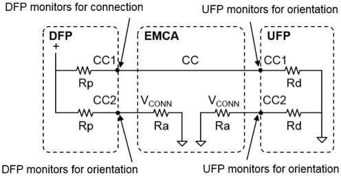
Figure 6. Type-C Connection/ Orientation Detection (Source: Cypress Semiconductor)
Rp and Rd termination resistors on the Type-C receptacle CC pins make it possible to detect the connection event and identify the orientation of the Type-C plugs in the receptacles. The DFP and UFP monitor both CC pins on the Type-C receptacle for a voltage change from their unterminated voltages to detect the connection event. The UFP also monitors for VBUS as a second indicator of a DFP connection. Both DFP’s and UFP’s can determine the Type-C cable plug orientation on their respective ends of the connection. This is possible because only one of the CC pins is connected through the cable. After the connection and orientation is detected, the other CC pin is repurposed by the DFP as VCONN for powering the electronics in the USB Type-C EMCA plug if an Ra termination resistor is detected.
Connecting two Type-C Dual Role Ports
Dual role Ports (DRP), as already discussed above, can operate as either a power Source or a Sink. A DRP exposes the Rp terminations on its CC wires when acting as the power source and exposes Rd terminations on its CC wires when acting as the power sink. DRP devices will initially toggle their state between DFP (by connecting Rp and disconnecting Rd ) and UFP (by disconnecting Rp and connecting Rd ) operation, until the complimentary termination is found at the port partner on one of the CC lines, for a successful Type-C connection detection as depicted in Figure 7.
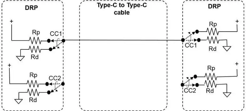
Figure 7. Type-C connection between two DRPs (Source: Cypress Semiconductor)
When a DRP device (e.g. PC) is connected to a power consumer (e.g. a mouse), a successful Type-C connection occurs when the DRP device (e.g. PC) exposes the Rp termination and the consumer, being a power sink, exposes Rd . Thus, the DRP port of the PC locks as a DFP (initially) in this case.
On the other hand, when a DRP device (e.g. PC) is connected to a power provider (e.g. a power adapter), a successful Type-C connection happens when the DRP device (e.g. PC) exposes Rd termination and the power adapter, being a power source, expose Rp . Thus the PC port locks as a UFP (initially) in this case.
When two DRPs are connected together, they accept the resulting DFP-to-UFP relationship achieved randomly. Both DRPs toggle their states between DFP and UFP as depicted in Figure 7. Whenever a successful Rp – Rd voltage divider is formed on one of the CC lines, the connection is established.
USB Power Delivery (PD) Protocol View
The USB Type-C specification allows for up to 15 W to be transferred from DFP to UFP on the VBUS and Ground signals. This 15 W can only be transmitted at 5 V when a “Type-C Only” device is used. Adding USB Power Delivery to a “Type-C Only” device makes a “Type-C PD” device which can raise the VBUS voltage above 5 Vo to a maximum of 20 V and raise the VBUS current to a maximum of 5 A.
When operating in a “Type-C Only” environment, the voltage divider of the Rp and Rd resistors that the DFP and UFP provide respectively determines the current limit of the VBUS power source. The UFP must detect this Rp /Rd voltage divider voltage and use it to determine the maximum current that can be drawn from the VBUS power source. This Rp /Rd voltage divider voltage is not static as the DFP can dynamically change its current limit as environmental variables of the charging ecosystem change. The UFP must always monitor this voltage and obey the new VBUS current limit that is dictated by the DFP.
This behavior of a “Type-C Only” device where the DFP dictates and a UFP obeys illustrates one weakness of the “Type-C Only” approach. Negotiation does not exist in a “Type-C Only” approach where a Type-C PD device has bidirectional negotiation of VBUS voltage and current levels. By adding USB-PD to a “Type-C Only” device and creating a “Type-C PD” device, you can achieve the necessary flexibility of VBUS power negotiation.
When USB PD is implemented, USB PD Bi-phase Mark Coded (BMC) carried on the CC wire is used for USB PD communications between USB Type-C ports. Figure 8 illustrates how the USB PD controller connects to the CC wire and introduces BMC signaling to the USB Type-C cable’s CC wire. In the figure, only one of the CC lines (that which is connected through the cable) is shown.
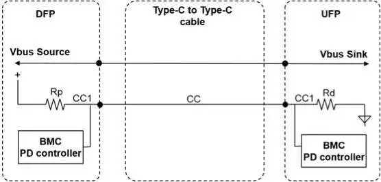
Figure 8. USB Power Delivery over Type-C (Source: Cypress Semiconductor)
An explicit power contract or agreement is reached between a Port Pair as a result of the Power Delivery negotiation process. The power delivery negotiation happens using PD Messages (defined by the USB-PD specification) over the CC wire in a Type-C connection.
USB Type-C and power delivery 101 – Power delivery protocol
As described in the first part of this two-part series, USB Type-C is the newly introduced and powerful interconnect standard for USB. When paired with the new Power Delivery (PD) specification, Type-C offers enhancements to the existing USB 3.1 interconnect that lower the cost and simplify the implementation of power delivery over USB. In this article, we describe the USB Type-C power delivery protocol.
Figure 9 shows the PD message format. All PD messages are transmitted at 300KHz +/- 10% over the CC line. The first 64 bits (Preamble ) are an alternating 1, 0 pattern so that the receiver can synchronize with the actual transmitted clock. The next 16-bit word (Address or Type ), contains the message address, indicating the message recipient or other type information (SOP* communication explained below). The next 16-bit field contains the message header, which is encoded as shown in Figure 9. The header field includes a data object count (#Data Objects). If the data object count is 0, then the message type is “control.” If it is 1 through 7, then up to seven 32-bit data objects follow, and the message type is “data.” A 32-bit CRC is transmitted, followed by a 4-bit end of packet (EOP) token that completes the message. If the calculated CRC is the same as the received CRC, then the Type-C device physical layer passes the decoded message up to its protocol layer for decoding. Refer to the USB-PD specification for more details on the message structure.
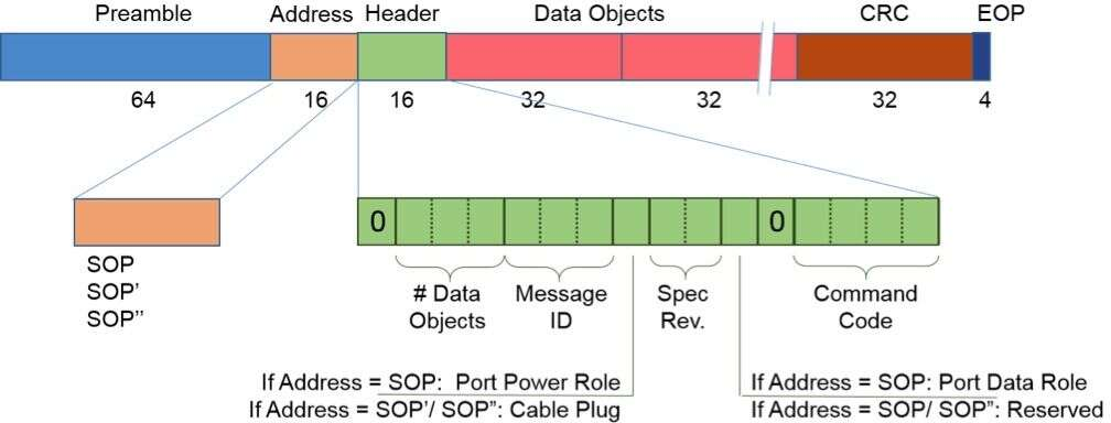
Figure 9. PD message format (Source: Cypress Semiconductor)
The USB-PD specification defines two types of Messages (see Table 4):
- Control Messages are short and manage the Message flow between Port Partners or for exchanging Messages that require no additional data.
- Data Messages exchange information between a pair of Port Partners. Data messages include exposing capabilities and negotiating power, Built-In-Self-Test (BIST), and custom messaging defined by the OEM.
Table 4. PD Message Types: Control and Data (Source: Cypress Semiconductor)
| Control Message | Description |
| GoodCRC | Message sent by the receiver to acknowledge that the previous Message was correctly received |
| GotoMin | It is a directive to the Sink Port to reduce its operating power level to the amount specified in the Minimum Operating Current field of its latest Sink Request Data Object |
| Accept | Sent by the recipient of certain messages like Request (during a power negotiation), DR_SWAP, PR_SWAP, VCONN _SWAP, etc. to signal that it is willing to do a power contract or role swaps |
| Reject | Sent by the recipient of certain messages like Request (sent by Sink during a power negotiation) to signal that it is unable to meet the power profiles requested by the Sink in Request message or as a reply to the messages like DR_SWAP, PR_SWAP, VCONN _SWAP, etc. to signal that it is unable to do role swaps |
| PS_RDY | [Power Supply Ready] Message sent by the Source (or by both the new Sink and new Source during the Power Role Swap sequence) to indicate its power supply has reached the desired operating condition |
| Get_Source_Cap | [Get Source Capability] Message sent by a Port to request the Source Capabilities and Dual-Role capability of its Port Partner (e.g. Dual-Role capable). The Port shall respond by returning a SourceCapabilities Message. A Sink Port, without Dual-Role capability, shall return a Reject Message |
| Get_Sink_Cap | [Get Sink Capability] Message sent by a Port to request the Sink Capabilities and Dual-Role capability of its Port Partner (e.g. Dual-Role capable). The Port shall respond by returning a Sink_Capabilities Message. A Source Port, without Dual-Role capability, shall return a Reject Message |
| DR_Swap | [Data Role Swap] Message used to swap the port’s data role (DFP / UFP) between the Port Partners both utilizing Type-C connectors while maintaining the direction of power flow over VBUS |
| PR_Swap | [Power Role Swap] Message used to swap the port power role (power provider / power consumer) between the Port Partners both utilizing Type-C connectors while maintaining the data role of the ports |
| Vconn_Swap | Message sent by either Port Partner to request an exchange of VCONN Source |
| Wait | Sent by the recipient of certain messages like Request (during a power negotiation), DR_SWAP, PR_SWAP, VCONN _SWAP, etc to signal that it is unable to meet the power profiles requested by the Sink in the Request message or unable to do role swaps at this point of time |
| SoftReset | Message initiated by either the Source or Sink to its Port Partner requesting a Soft Reset. It is used to recover from PD Protocol Layer errors. |
| Data Message | Description |
| SourceCapabilities | A Source Port shall report its capabilities in a series of 32-bit Power Data Objects as part of a SourceCapabilities Message. Power Data Objects (PDOs) are used to convey a Source Port’s capabilities to provide power |
| Request | Message sent by a Sink to request power, typically during the request phase of a power negotiation. The Request Data Object shall be returned by the Sink making a request for power |
| SinkCapabilites | A Sink Port shall report power level capabilities in a series of 32-bit Power Data Objects. These are returned as part of a SinkCapabilities Message in response to a Get_Sink_Cap Message. This is similar to that used for Source Port capabilities with equivalent Power Data Objects for Fixed, Variable and Battery Supplies as defined in this section. Power Data Objects are used to convey the Sink Port’s operational power requirements |
| BIST | [Built In Self-Test] Message sent to request the Port to enter Physical Layer test mode |
| VendorDefined | [Vendor Define Message – VDM] Message provided to allow vendors to exchange information outside of that defined by the USB-PD specification |
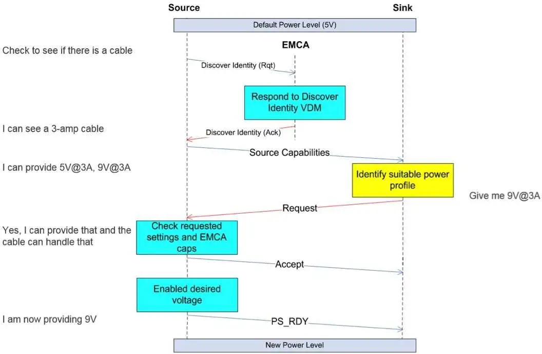
Figure 10. Successful Power Negotiation. Note: Rqt – Request; Ack – Acknowledge; VDM – Vendor Defined message (Source: Cypress Semiconductor)
Figure 10 shows the message flow during a successful power negotiation between any two generic PD-enabled Type-C devices connected by an Electronically Marked Type-C cable (see Figure 11). Note that each command and data message is acknowledged by the receiver of the message, which sends a GoodCRC response back to the initiator (not shown in Figure 10).
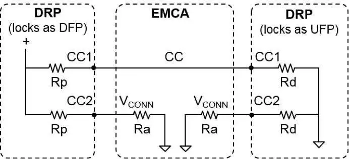
Figure 11. Type-C connection with EMCA (Source: Cypress Semiconductor)
- The DRP, which got locked as a DFP (Source), first discovers the presence of an EMCA attached due to the presence of Ra. It queries for the characteristics of the cable by sending the DiscoverIdentity
- The cable responds with the cable characteristics using the DiscoverIdentity ACK response message (see Figure 10).
- The DFP (Source) also detects the presence of a UFP (Sink) due to the Rd The DFP (Source) then sends the source capabilities message to the UFP (Sink) that represents the DFP (Source) power supply’s present capabilities as in Figure 10. In Figure 10, this message sends out the power supply capability as the ability to source 5 V at 3 A and 9 V at 3 A.
- The UFP (Sink) then uses a Request message for, in this case, 3 A of current at 9 V.
- The DFP (Source) sends an Accept message and then sends a PS_RDY message as an indication that the source is ready to start sourcing the new power level on VBUS .
The UFP (Sink), on detecting VBUS , could start enumeration if it had USB data channels.
SOP* Communication in USB PD
Power Delivery communication starts with sequences of special symbols called K-code markers to delineate the start of a packet. K-codes are provided by the 4b5b line-encoding scheme used in PD communication to delineate packet boundaries.
In addition to encoding data, K-codes are used for special control functions, such as a hard reset or cable reset. The special K-code sequence signifying the start of sequence is called the Start Of Packet (SOP). Three sequences are defined: SOP, SOP’, and SOP’’. SOP* is used to refer all the three SOP sequences. Figure 12 defines and differentiates SOP* packets:
- SOP Packet : Any Power Delivery packet that starts with an SOP sequence. The communication between Port Partners (DFP and UFP) uses SOP packets. These packets are not recognized by either Cable Plug.
- SOP’ Packet: Any Power Delivery packet that starts with an SOP’ sequence used to communicate with a Cable Plug. SOP’ packets are recognized by the electronics in the Cable Plug attached to the DFP (cable plug marked SOP’ in Figure 12) and are not recognized by the other Cable Plug or the port partner in UFP.
- SOP’’ Packet: Any Power Delivery packet that starts with an SOP’’ sequence used to communicate with a Cable Plug when SOP’ packets are being used to communicate with the cable plug at the other end. SOP’’ packets are recognized only by the electronics in the Cable Plug attached to the UFP (cable plug marked SOP” in Figure 12) and are not recognized by the other Cable Plug attached to the DFP or the port partner in UFP.
Response to SOP” packets by the cable plug attached to UFP is optional, but the response to SOP’ packets by the cable plug attached to DFP is mandatory in an EMCA. Note that the term “Cable Plug” in the SOP’/SOP’’ communication case is used to represent a logical entity in the cable that is capable of PD communication. These entities may or may not be physically located in the plug.
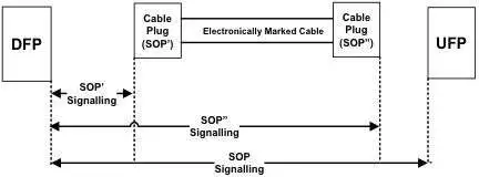
Figure 12. SOP* Communication (Source: Cypress Semiconductor)
SOP* communication takes place over a single wire (CC). This means that SOP* communication periods must be coordinated to prevent important communications from being blocked. Communications between the Port Partners (SOP packets) take precedence, implying that communications with the Cable Plug (SOP’/ SOP” packets) can be interrupted. See the USB PD specification for more details.
Role Swapping in USB-PD
Before the USB-PD specification came into being, the USB host (such as a laptop, for example) was always the power provider and the USB device (i.e., a mouse) was always the power consumer. Charging the battery of the host computer was considered a separate action. The PD specification greatly improves the USB ecosystem and defines power roles (VBUS Source and Sink) that are independent of the data roles (USB host and USB device). This includes the ability to swap power and data roles independently. An example of such versatile behavior is a wall mounted peripheral device such as a monitor can charge the battery of a USB host such as a notebook or PC.
The PD specification defines three types of role swaps:
- Data Role Swap (DR_SWAP): Exchange the DFP (Host) and UFP (Device) roles between Port Partners over the USB Type-C connector. This does not swap the Rp and Rd terminations on the CC line of the port partners as the port power role remains intact.
- Power Role Swap (PR_SWAP): Exchange the Source and Sink roles between Port Partners. This also swaps the Rp and Rd terminations on the CC line of the port partners.
- VCONN Swap (VCONN_SWAP): Exchange the VCONN (cable plug power) Source between Port Partners.
Table 5 summarizes the behaviors of a port in response to the three USB PD swap commands.
Table 5. USB PD Swapping Port Behavior Summary (Source: Cypress Semiconductor)
| DFP/ UFP Data Roles | Rp / Rd | VBUS Source/ Sink | VCONN Source | |
| PR_SWAP | Unchanged | Swapped | Swapped | Unchanged |
| DR_SWAP | Swapped | Unchanged | Unchanged | Unchanged |
| VCONN _SWAP | Unchanged | Unchanged | Unchanged | Swapped |
Figure 13 shows the message sequence during a DFP-initiated successful DR_SWAP. It can be initiated by either the DFP or the UFP. One example scenario that will need DR_SWAP for proper operation is when a USB Type-C Monitor (DRP) locks as a DFP/ Source initially when connected to a USB Type-C host (DRP). Thus the monitor is sourcing power to the Type-C host. For proper functionality, the Type-C monitor should be UFP with the Type-C host as DFP. DR_SWAP enables the swap to be initiated by the monitor.
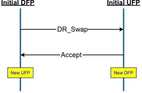
Figure 13. DFP initiated DR_SWAP (Source: Cypress Semiconductor)
Figure 14 shows the message sequence during a Source initiated successful PR_SWAP. It can be initiated by either the source or the sink. One example scenario that will need PR_SWAP for proper operation is when a USB Type-C Monitor (DRP) locks as a UFP/ Sink initially when connected to a USB Type-C laptop (USB host/ DRP). In this case, the monitor initially sinks power from the Type-C host. PR_SWAP is needed to enable the monitor to charge the Type-C laptop. This swap can be initiated either by the Type-C monitor or the laptop.
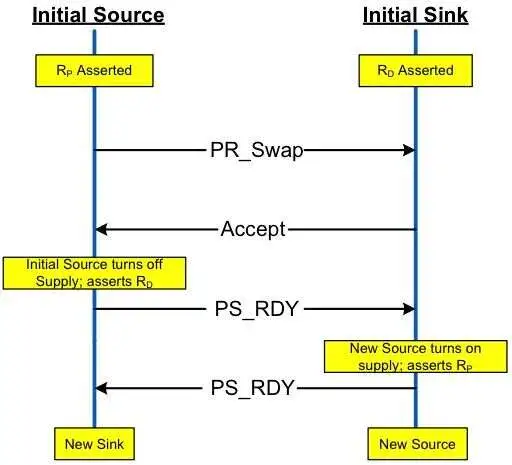
Figure 14. Source initiated PR_SWAP (Source: Cypress Semiconductor)
Figure 15 shows the message sequence during a DFP initiated successful VCONN _SWAP. It can be initiated by either the current VCONN source or VCONN sink. As shown in the figure, both sources will be on at the same time for a short while following the Accept message. This is because the new VCONN source turns on following the Accept message and before the PS_RDY instance, and the old VCONN source turns off after the PS_RDY instance. This sequence of VCONN powering is, as per the USB-PD specification, to ensure that the cable controller always remains powered. Furthermore, to avoid the two VCONN sources being on at the same time, the specification mandates an isolation element between the two VCONN sources (e.g. a diode) to select a particular source among the two when both are available.
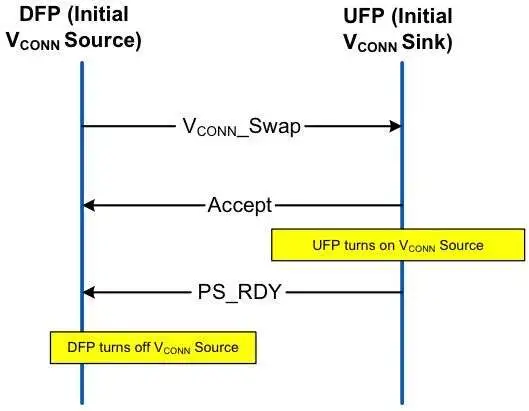
Figure 15. DFP initiated VCONN _SWAP (Source: Cypress Semiconductor)
This article has provided a high level view of the basics of the USB Type-C and Power Delivery (PD) specifications. For additional information, see Type-C Essentials, Type-C Resources, and the USB Type-C and Power Delivery FAQ.
References
- Specifications: Type-C Specification, USB-Power Delivery Specification
- Other web links: www.cypress.com/type-C, Designing a Type-C Electronically Marked Cable
Gayathri Vasudevan is a Staff applications engineer at Cypress Semiconductor, Bangalore. Gayathri is responsible for supporting customers on all wired USB products, developing specifications for next generation products, and creating solution demos, application notes and other collateral for new products. She has a degree in electronics and communication engineering.